Text to CAD - Online Skill
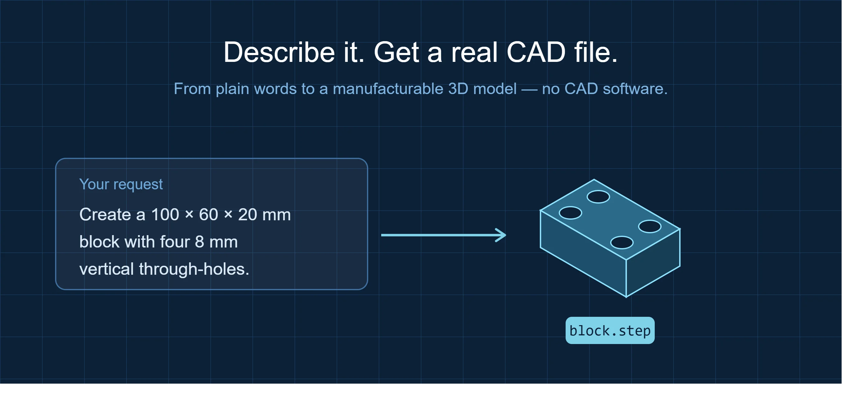
Most "AI CAD" tools hand you a rough mesh or a picture you still have to rebuild by hand. This one delivers a real, parametric STEP solid — the same file format engineers send to CNC shops and 3D printers — generated from a single sentence and checked against your exact dimensions before you ever see it.
Describe the part. Get a clean, manufacturable file. No modeling software, no learning curve.
Who It's For
- Mechanical & product designers who need a part modeled now, not after an hour in SolidWorks
- Hardware engineers & makers prototyping brackets, mounts, housings, and fixtures
- 3D-printing & CNC users who want a watertight STEP/STL ready to slice or machine
What You Get
- A single, clean STEP solid — the primary format for CAD and manufacturing
- Optional STL / 3MF / GLB export for 3D printing or web preview
- A dimension report — bounding box, hole count, and key measurements verified against your spec
- A rendered snapshot of the finished part so you can eyeball it instantly
How It Works
- Describe the part in plain words — outer size, thickness, holes, bores, bolt patterns, chamfers.
- The part is built as a true parametric solid and automatically checked: dimensions, hole positions, and a single closed body.
- You receive the STEP file, a measurement summary, and a preview image — ready to open in FreeCAD, Fusion 360, or SolidWorks, or send straight to a printer or CNC.
Most parts come back in a couple of minutes. Add reference dimensions, a drawing, or a target format to refine.
Example Requests
"Create a 100 × 60 × 20 mm block with four 8 mm vertical through-holes."
A clean rectangular solid with four corner holes, verified at 100 × 60 × 20 mm.
"80 mm flange, 10 mm thick, 30 mm central bore, six 6 mm bolt holes on a 60 mm bolt circle."
An annular flange with a concentric bore and an evenly spaced bolt pattern, dimension-checked.
"Stepped bushing: Ø50 × 8 mm flange, Ø40 × 30 mm body, Ø20 through-hole."
A single solid with the correct shoulder and total height verified at 38 mm.
Formats & Compatibility
STEP / STP (primary) · STL · 3MF · GLB. Opens in FreeCAD, Fusion 360, SolidWorks, Onshape, and any STEP-compatible tool. Ready for CNC machining and FDM or resin 3D printing.
What Makes This Different
- vs. CAD software (SolidWorks / Fusion 360): No license, no learning curve, no hours of modeling — describe it and get the file.
- vs. outsourced modeling: Minutes instead of days, at a fraction of the cost, with dimensions verified automatically.
- vs. other text-to-CAD tools: You get a real, editable STEP solid checked against your numbers — not a lossy mesh or a rendering you can't manufacture.
Best Suited For
Prismatic and machined-style mechanical parts: brackets, flanges, bushings, spacers, plates, enclosures, holes, bores, counterbores, chamfers, and bolt patterns — exactly the geometry that powers most real-world hardware and fixtures.